In the previous three articles, we built the IPsec VPN concept step by step.
We looked at how a site-to-site VPN works, how IKE Phase 1 establishes the relationship between the VPN peers, and how Phase 2 creates the IPsec security association used to protect traffic.
Now comes the part that causes a lot of real-world VPN problems.
The tunnel is UP, but the traffic still doesn’t work.
You check the IKE SA. It’s up.
You check the IPsec SA. It’s up.
But PC-1 still can’t ping PC-2.
At this point, the problem may have nothing to do with encryption.
The firewall still has to route the packet, evaluate security policy, decide whether NAT should be applied, and send the packet into the VPN tunnel.
That’s what we will look at in this article.
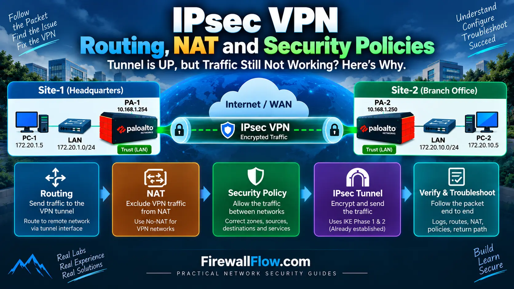
Our Site-to-Site IPsec VPN Lab
We are continuing with the same lab topology used throughout this series.
Site-1
- LAN:
172.20.1.0/24 - PC-1:
172.20.1.5 - Firewall LAN:
172.20.1.254 - Firewall WAN:
10.168.1.254
Site-2
- LAN:
172.20.10.0/24 - PC-2:
172.20.10.5 - Firewall LAN:
172.20.10.254 - Firewall WAN:
10.168.1.250
Our goal is:
172.20.1.5
     |
     ↓
   PA-1
     |
 IPsec VPN
     |
   PA-2
     |
     ↓
172.20.10.5
The protected networks are:
172.20.1.0/24 ↔ 172.20.10.0/24The VPN Tunnel Being UP Is Not Enough
This is probably the most important point in this article.
A VPN can show:
IKE SA      = UP
IPsec SA    = UP
and still not pass traffic.
Why?
Because establishing the tunnel only solves part of the problem.
The firewall still needs to answer several questions:
- Where should this packet go?
- Should NAT be applied?
- Is the traffic allowed by security policy?
- Does the traffic match the VPN’s protected networks?
- Is the return traffic routed correctly?
If any one of these is wrong, the application can fail.
So when troubleshooting a site-to-site VPN, don’t immediately assume the IPsec configuration is the problem.
Start following the packet.
IPsec provides network-layer security, but a working VPN also depends on correct network design and implementation. For broader implementation guidance, see the NIST Guide to IPsec VPNs.
Step 1: IPsec VPN Routing
Let’s say PC-1 sends:
Source:      172.20.1.5
Destination: 172.20.10.5
PC-1 first checks its routing table.
Because 172.20.10.5 is on a different subnet, PC-1 sends the packet to its default gateway:
172.20.1.254The packet reaches PA-1.
Now PA-1 has to decide:
Where should I send traffic destined for
172.20.10.5?
This is where routing becomes important.
Why Do We Need a Route?
The firewall needs a route telling it that:
172.20.10.0/24is reachable through the VPN tunnel.
In a route-based VPN, this is commonly done using a tunnel interface and a routing entry.
Conceptually:
Destination:
172.20.10.0/24

Next hop/interface:
IPsec tunnel interface
Without an appropriate route, PA-1 may not send the packet into the VPN at all.
It could instead use another route, or simply have no valid route.
This is why creating the IPsec tunnel alone doesn’t automatically solve routing.
Route-Based VPN and the Tunnel Interface
In our Palo Alto lab, we will use a route-based VPN design.
A tunnel interface provides a logical Layer 3 interface for the VPN.
Think of it as a logical path:
PA-1
 |
 | tunnel.1
 |
IPsec VPN
 |
 | tunnel.1
 |
PA-2
The encryption happens through the IPsec configuration, while the routing table determines which traffic should use the tunnel interface.
This separation is useful because routing and encryption are handled as related but separate parts of the packet flow.
Step 2: Security Policy
Once PA-1 receives the packet, routing isn’t the only thing it checks.
The firewall also needs to determine whether the traffic is allowed.
For our example:
Source Zone:
Site-1 LAN

Destination Zone:
VPN

Source:
172.20.1.0/24

Destination:
172.20.10.0/24
The security policy should allow the required traffic.
For example:
Source:      172.20.1.0/24
Destination: 172.20.10.0/24
Application: Required applications
Service:     Required services
Action:      Allow
The exact zones and policy structure depend on the firewall design.
The important point is that IPsec encryption does not bypass the firewall’s security policy.
The traffic still has to be permitted.
Why Security Policy Causes So Many VPN Problems
Suppose Phase 1 and Phase 2 are both UP.
You run:
ping 172.20.10.5and it fails.
A common reaction is:
“The VPN must be broken.”
But the VPN may be working perfectly.
The security policy could simply be denying the packet.
Check the traffic log.
You want to know:
- Which rule matched?
- Was the traffic allowed or denied?
- What source zone was identified?
- What destination zone was identified?
- What source and destination IPs did the firewall see?
This is much more useful than repeatedly changing the IPsec configuration.
Step 3: NAT
NAT is another common reason for VPN traffic problems.
For normal Internet traffic, you may have a rule such as:
172.20.1.0/24
      ↓
Source NAT
      ↓
WAN IP
That makes sense for Internet access.
But VPN traffic is different.
For traffic going to:
172.20.10.0/24you normally want the original source address to remain:
172.20.1.5rather than translating it to the firewall’s WAN address.
So VPN traffic is commonly configured with a NAT exemption/no-NAT rule.
Conceptually:
172.20.1.5
     |
     | No NAT
     ↓
172.20.10.5
The exact NAT behavior and rule processing depend on the firewall platform and configuration.
Why NAT Can Break a VPN
Imagine PC-1 sends:
172.20.1.5 → 172.20.10.5But a generic outbound source-NAT rule translates the source:
172.20.1.5
     ↓
10.168.1.254
Now the packet no longer looks like the traffic originally defined for the VPN.
Instead of:
172.20.1.0/24 → 172.20.10.0/24the firewall may now be dealing with:
10.168.1.254 → 172.20.10.5That can prevent the traffic from matching the intended VPN configuration.
This is why VPN NAT rules need to be designed carefully.
NAT Rule Ordering Matters
Another common problem is having the correct NAT exemption rule but placing it after a broader Internet NAT rule.
For example:
Rule 1:
172.20.1.0/24 → 172.20.10.0/24
No NAT

Rule 2:
172.20.1.0/24 → Any
Source NAT
This allows VPN traffic to match the specific rule first.
If the broad NAT rule is evaluated first, the VPN traffic may be translated before it reaches the intended processing stage.
The exact packet-processing sequence varies by firewall platform, so don’t assume that every vendor handles NAT and policy evaluation in exactly the same way.
Following a Packet Through Our VPN
Now let’s put routing, NAT, and security policy together.
PC-1 sends:
Source:      172.20.1.5
Destination: 172.20.10.5
1. PC-1 Sends the Packet
PC-1 sees that 172.20.10.5 is remote and sends the packet to:
172.20.1.2542. PA-1 Receives It
PA-1 receives the packet from the Site-1 LAN.
3. Security Policy Is Evaluated
The firewall checks whether the traffic from Site-1 to the VPN destination is allowed.
4. NAT Is Evaluated
The VPN traffic should match the appropriate no-NAT/exemption rule in our design.
5. Routing Is Checked
PA-1 has a route for:
172.20.10.0/24through the tunnel interface.
6. IPsec Protects the Packet
The packet is encapsulated and encrypted.
Conceptually:
Original:
172.20.1.5 → 172.20.10.5

        ↓

IPsec encryption

        ↓

WAN:
10.168.1.254 → 10.168.1.250
7. PA-2 Receives the Packet
PA-2 decrypts the IPsec packet and processes the original packet.
8. PA-2 Routes It to PC-2
PA-2 knows:
172.20.10.0/24is directly connected to its LAN.
The packet is sent to:
172.20.10.5That’s the complete high-level flow.
Don’t Forget the Return Path
This is one of the first things I check when traffic works in one direction but not the other.
PC-2 needs to reply:
172.20.10.5 → 172.20.1.5PA-2 must know that:
172.20.1.0/24is reachable through the VPN.
So both firewalls need the correct routing information.
PA-1:
172.20.10.0/24 → VPN

PA-2:
172.20.1.0/24 → VPN
If PA-1 has the route but PA-2 doesn’t, the first packet may reach PC-2 but the reply won’t return correctly.
This is a classic asymmetric routing problem.
A Simple Troubleshooting Flow
When the tunnel is UP but traffic isn’t passing, work through the packet path instead of changing everything at once.
Check 1 — Can the Endpoints Reach Their Gateways?
From PC-1:
ping 172.20.1.254From PC-2:
ping 172.20.10.254If this fails, fix the LAN problem first.
Check 2 — Is the Route Present?
On PA-1, verify the route toward:
172.20.10.0/24On PA-2, verify the route toward:
172.20.1.0/24Check 3 — Is Security Policy Allowing the Traffic?
Look at the firewall traffic logs.
Don’t just check whether a rule exists.
Check whether that rule is actually matching.
Check 4 — Is NAT Being Applied?
Verify that VPN traffic isn’t being translated by a general Internet NAT rule.
Check 5 — Does Traffic Match the VPN?
Make sure the source and destination networks match the configured traffic selectors or Proxy IDs.
Check 6 — Check the Return Traffic
If one direction works but the other doesn’t, inspect the return route and return security policy.
Common VPN Routing, NAT and Policy Mistakes
Missing Route
The tunnel is established but there is no route toward the remote network.
Wrong Route
The firewall has a route, but it points to the wrong interface or next hop.
NAT Applied to VPN Traffic
The source address is translated when it should remain unchanged.
Wrong Security Zone
The policy is written for the wrong source or destination zone.
Policy Below a Broader Deny Rule
The correct allow rule exists but another rule is being matched first.
Missing Return Route
The remote firewall receives the traffic but doesn’t know how to return it.
Overly Broad NAT Rule
A general Internet NAT rule catches VPN traffic because the VPN-specific no-NAT rule doesn’t match first.
A Useful Way to Troubleshoot
When troubleshooting, break the problem into layers:
PC
 ↓
Gateway
 ↓
Routing
 ↓
Security Policy
 ↓
NAT
 ↓
IPsec Tunnel
 ↓
Remote Firewall
 ↓
Remote Routing
 ↓
Remote Security Policy
 ↓
Remote Host
Don’t jump directly to the IPsec configuration.
If PC-1 can’t even reach its default gateway, there is no reason to troubleshoot Phase 2.
If Phase 2 is UP but the traffic log shows a deny, investigate the security policy.
If the policy allows the traffic but the packet is being NATed incorrectly, investigate NAT.
This approach saves a lot of time.
What We Have Learned
At this point in the series, we have covered the major pieces required for a working site-to-site VPN:
- Part 1: What site-to-site IPsec VPN is and how it works
- Part 2: IKE Phase 1 and peer authentication
- Part 3: IPsec Phase 2, PFS and traffic selectors
- Part 4: Routing, NAT and security policies
The important lesson from this article is simple:
A VPN tunnel being UP doesn’t guarantee that applications will work.
Routing decides where the packet goes.
Security policy decides whether the firewall allows it.
NAT can change the packet and potentially prevent it from matching the VPN.
And the return path must work as well.
Once you start following the packet through these stages, VPN troubleshooting becomes much less of a guessing game.
Frequently Asked Questions
Do I need a route for the remote VPN network?
In a route-based VPN, yes. The firewall needs routing information that directs traffic for the remote network toward the tunnel interface.
Should VPN traffic be NATed?
Typically, site-to-site VPN traffic is configured so that the original private source and destination addresses are preserved. The exact implementation depends on the firewall design.
Can a VPN be UP while traffic is blocked?
Yes. The IKE and IPsec SAs can be established while security policy, routing, NAT, or endpoint configuration prevents traffic from passing.
Why is the return route important?
The remote host needs a path back to the original source network. If the return route is missing, communication may work in one direction but fail as a complete connection.
Which should I check first when VPN traffic fails?
Start with basic connectivity and routing, then check security policy, NAT, VPN traffic matching, and finally the return path. Use firewall logs and packet captures when necessary.
What’s Next?
We now understand how the VPN works and what happens to the packet before, during, and after it enters the IPsec tunnel.
There is only one major part left in this series.
In Part 5, we will stop talking about the VPN only from a theoretical perspective and actually configure it.
We’ll take the same two Palo Alto firewalls from our lab and configure:
- IKE Gateway
- IKE Crypto Profile
- IPsec Crypto Profile
- Tunnel Interface
- IPsec Tunnel
- Routing
- Security Policies
- NAT exemption
- Proxy IDs/traffic selectors where required
- VPN verification
- Connectivity testing
- Troubleshooting
We’ll also follow the packet from PC-1 (172.20.1.5) to PC-2 (172.20.10.5) and verify that the traffic is actually passing through the encrypted tunnel.
That is where all four previous articles come together.

Cybersecurity blogger with a focus on firewalls, network security, and tech trends making security simple for everyone, from IT pros to curious minds.