In the previous articles, we covered how site-to-site IPsec VPN works, how IKE Phase 1 and Phase 2 are negotiated, and how routing, NAT, and security policies affect VPN traffic.
Now let’s configure the VPN in a real Palo Alto lab.
This lab uses two Palo Alto firewalls running in EVE-NG. Both firewalls use a route-based IPsec VPN, with tunnel.2 used as the logical tunnel interface.
The VPN is already configured and working, so this article focuses on the actual configuration and verification rather than repeating the IPsec theory covered earlier.
Lab Topology
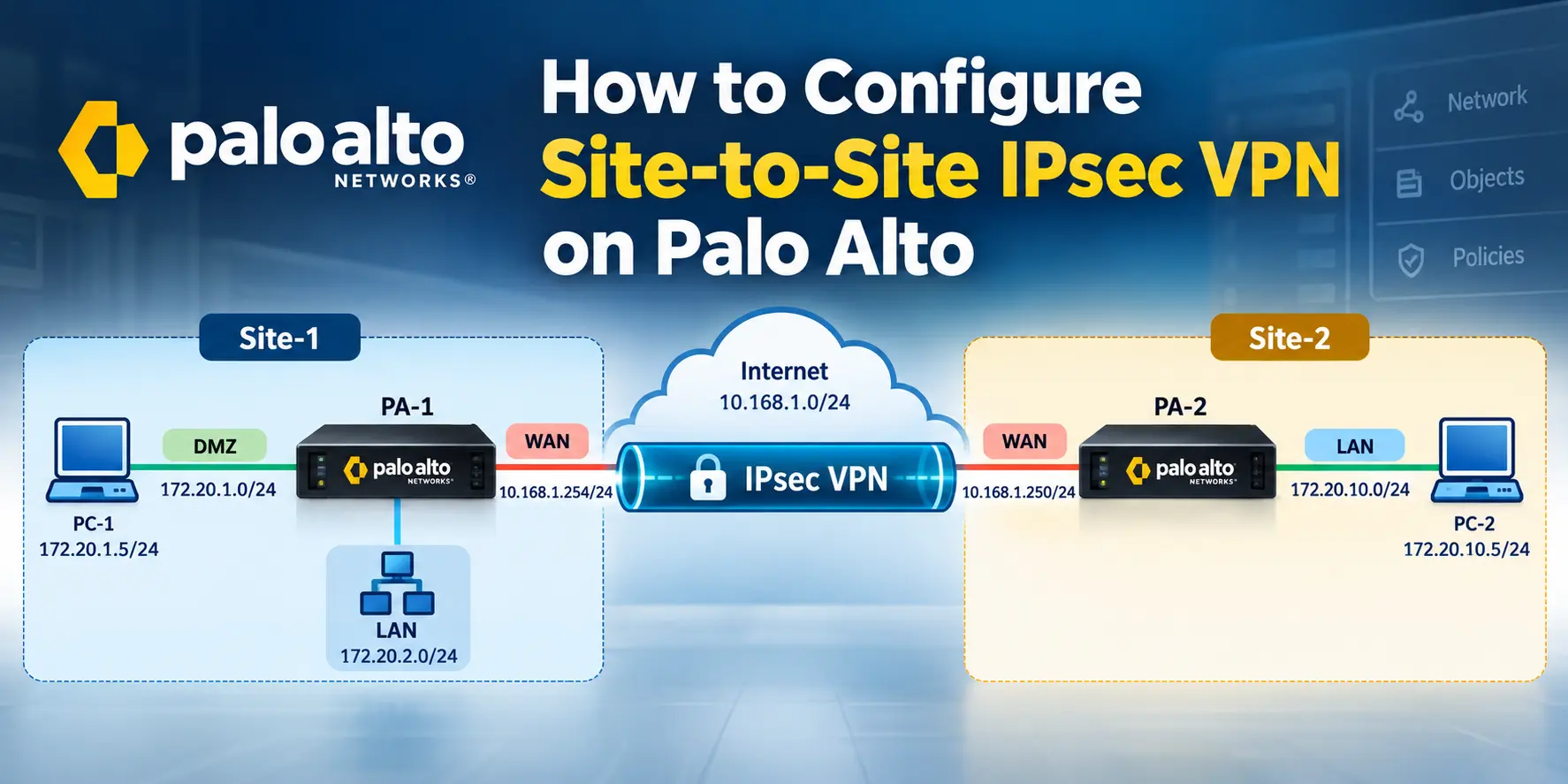
The lab has two separate networks connected through two Palo Alto firewalls. Site-1 uses 172.20.1.0/24 as its DMZ network, while the Site-1 LAN is 172.20.2.0/24.
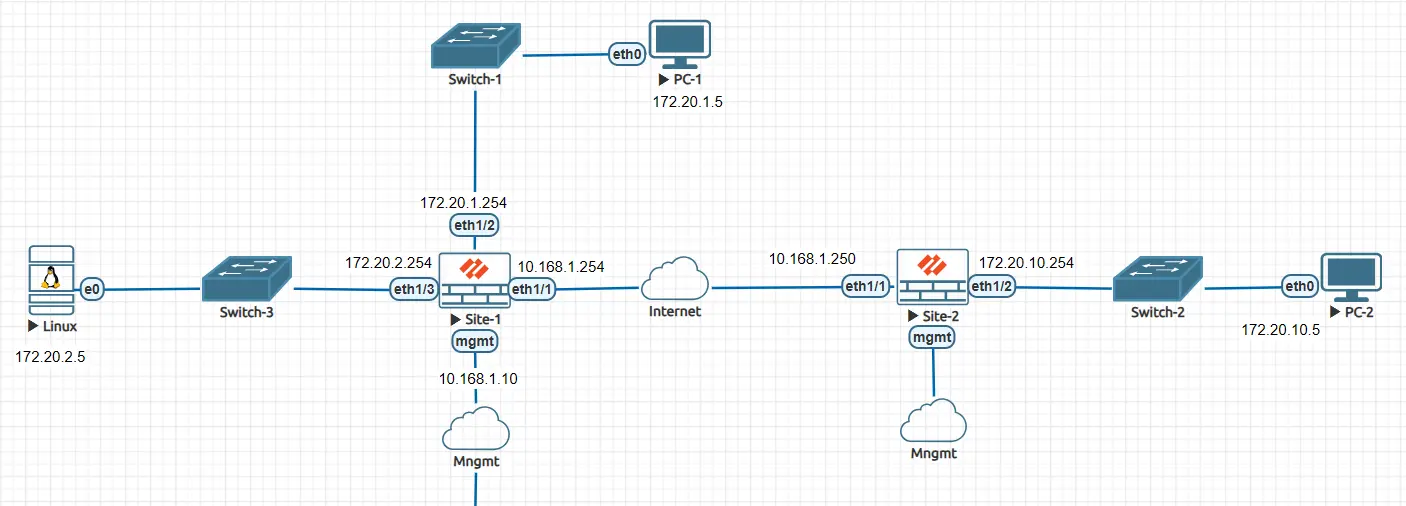
The addressing used in the lab is:
| Device | Interface | IP Address | Purpose |
|---|---|---|---|
| PC-1 | eth0 | 172.20.1.5/24 | Site-1 DMZ client |
| PA-1 | ethernet1/2 | 172.20.1.254/24 | Site-1 DMZ |
| PA-1 | ethernet1/3 | 172.20.2.0/24 | Site-1 LAN |
| PA-1 | ethernet1/1 | 10.168.1.254/24 | Site-1 WAN |
| PA-2 | ethernet1/1 | 10.168.1.250/24 | Site-2 WAN |
| PA-2 | ethernet1/2 | 172.20.10.254/24 | Site-2 LAN |
| PC-2 | eth0 | 172.20.10.5/24 | Site-2 client |
The 10.168.1.0/24 network represents the WAN/Internet segment in this EVE-NG lab. It is a simulated network used to connect the two firewalls.
Palo Alto Site-1 Configuration
The first firewall, PA-1, connects the 172.20.1.0/24 DMZ network and the 172.20.2.0/24 LAN to the WAN.
Step 1: Configure the Network Interfaces
On PA-1, the WAN interface is ethernet1/1 and the DMZ interface used by PC-1 is ethernet1/2. The Site-1 LAN uses ethernet1/3.
The relevant configuration is:
ethernet1/1
IP: 10.168.1.254/24
Zone: WAN

ethernet1/2
IP: 172.20.1.254/24
Zone: DMZ

ethernet1/3
Network: 172.20.2.0/24
Zone: LAN
Both interfaces are part of the default virtual router.

The DMZ interface is the default gateway for PC-1. The WAN interface is used to establish the IKE/IPsec connection with the second firewall.
Step 2: Create the Tunnel Interface
Because this is a route-based VPN, we need a logical tunnel interface.
On PA-1, the VPN uses:
Tunnel Interface: tunnel.2
Virtual Router: default
Security Zone: VPN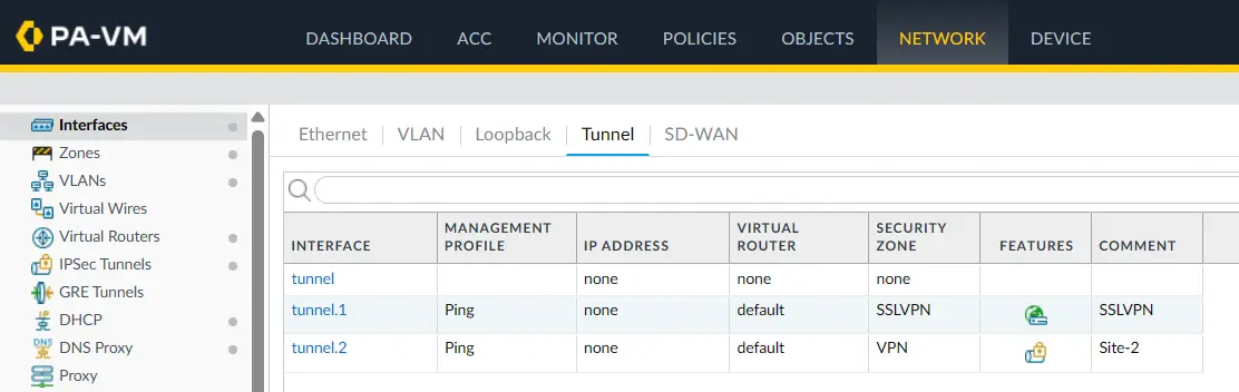
The tunnel interface is important because routing uses it to send traffic toward the remote network.
For example, traffic destined for 172.20.10.0/24 will eventually be routed to tunnel.2.
Step 3: Configure the IKE Crypto Profile
The IKE Crypto Profile defines the parameters used when the two firewalls establish the IKEv2 security association.
In this lab, the profile is configured with:
Profile: IKEcrypto

DH Group:       group14
Encryption:     aes-256-cbc
Authentication: sha256
Key Lifetime:   8 hours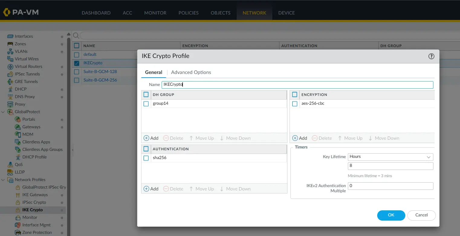
Both firewalls must have compatible IKE parameters. If the proposals don’t match, IKE Phase 1 will not establish successfully.
Step 4: Configure the IKE Gateway
The IKE Gateway defines the remote VPN peer and how the two firewalls authenticate with each other.
For this lab, the PA-1 gateway points toward the WAN address of PA-2:
Local IP:  10.168.1.254
Peer IP:   10.168.1.250
Version:   IKEv2 only
Authentication is based on a pre-shared key.
The local and peer identification are also based on the IP addresses.
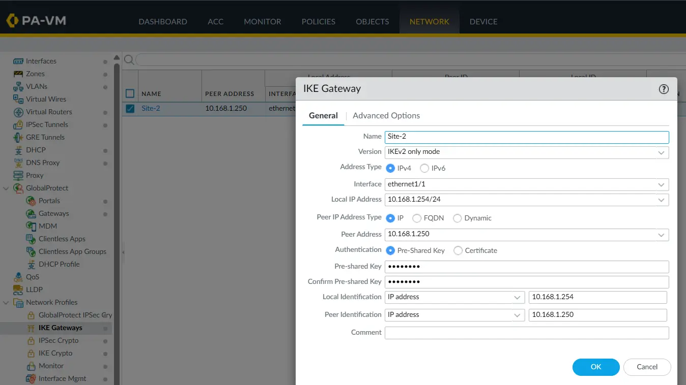
The pre-shared key is intentionally not shown in the article. When publishing screenshots from a real environment, never expose an actual VPN pre-shared key.
IKE Gateway Advanced Options
The lab also has NAT Traversal enabled and an IKEv2 liveness check configured.
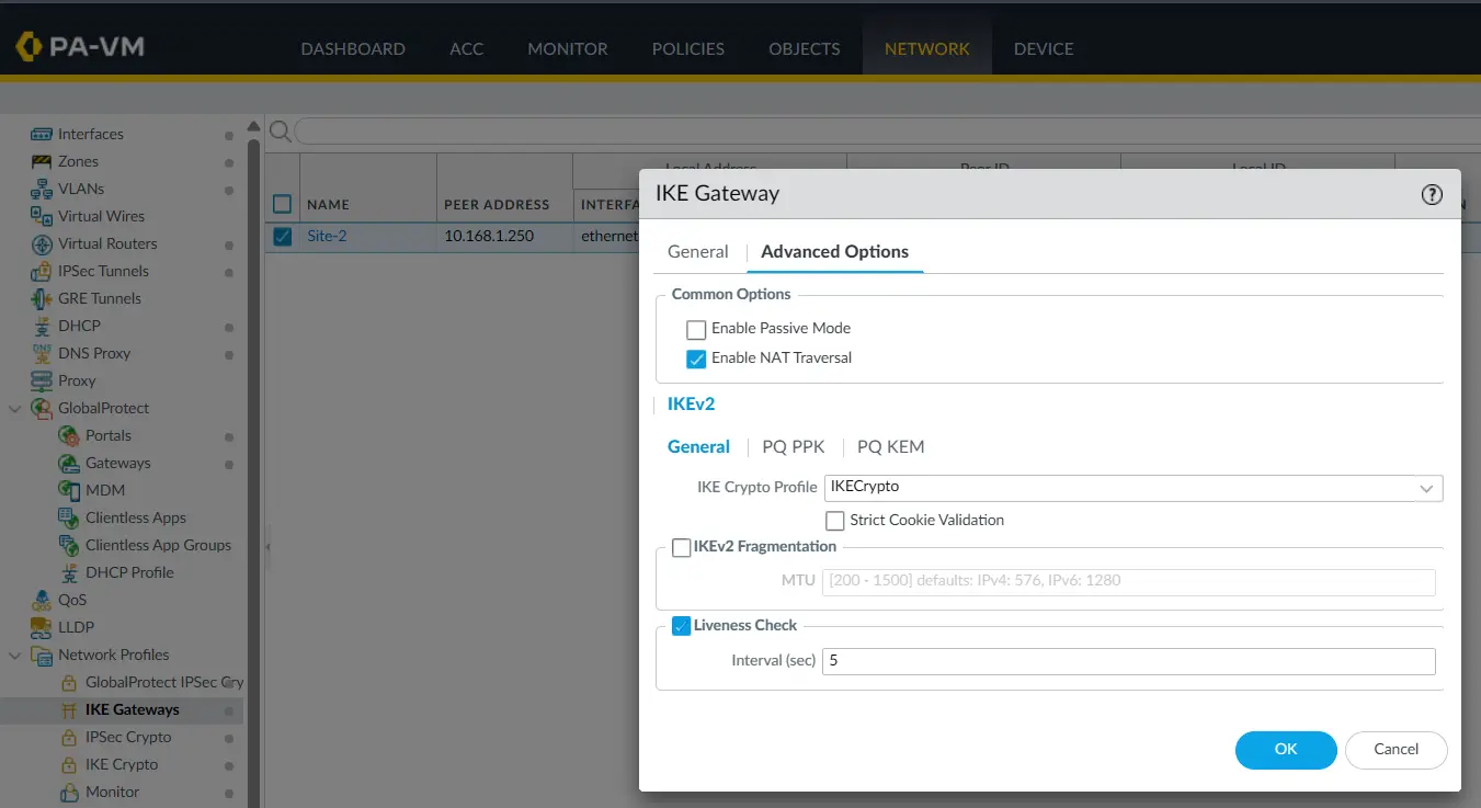
The liveness check allows the firewall to periodically verify that the IKE peer is still reachable.
Step 5: Configure the IPsec Crypto Profile
After IKE establishes the secure control channel, the IPsec parameters define how the actual data traffic is protected.
The lab uses:
IPsec Protocol: ESP

Encryption:     aes-256-cbc
Authentication: sha256

DH Group:       group14
Lifetime:       8 hours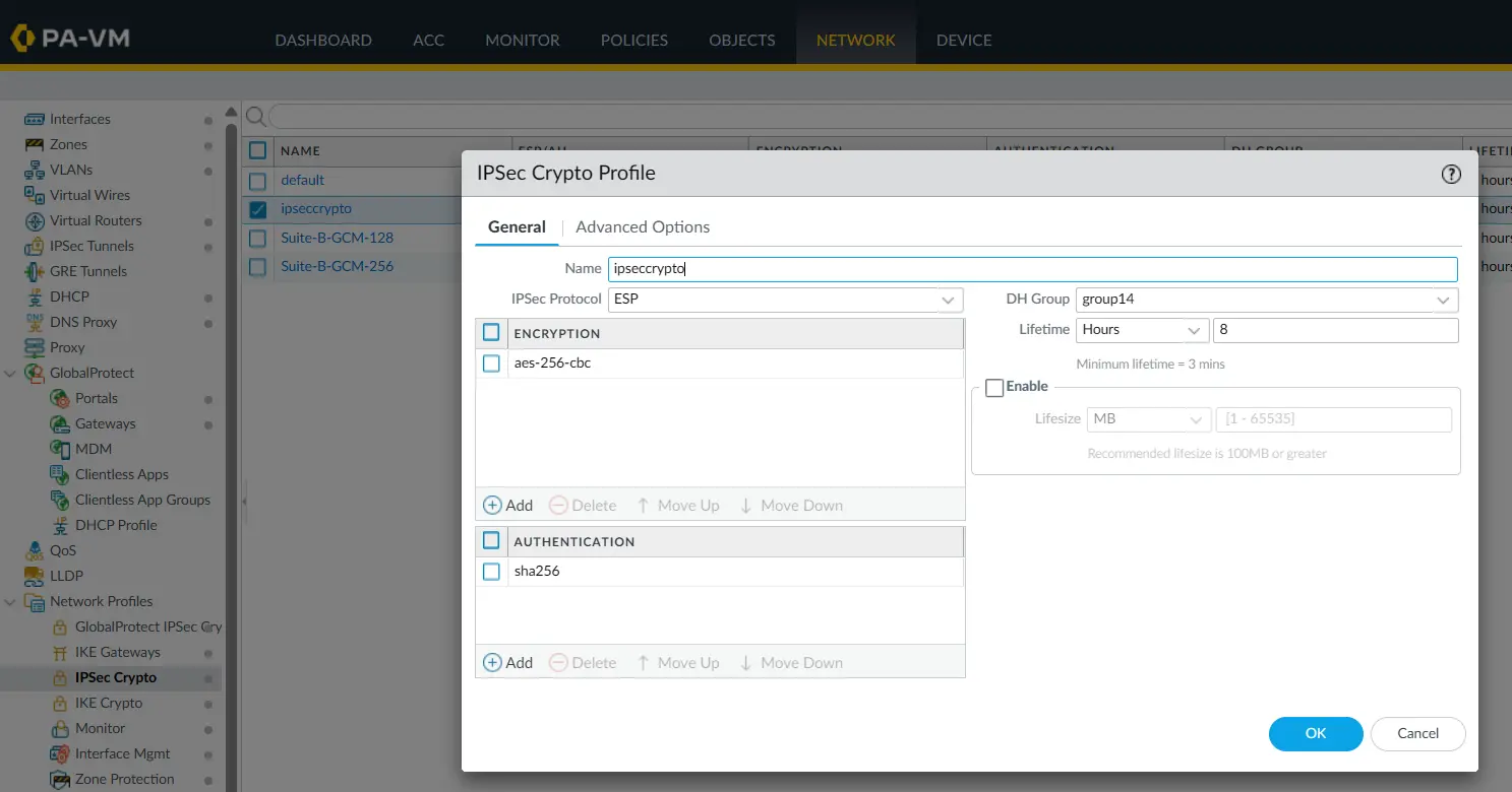
ESP is used because it provides encryption and integrity protection for the traffic carried through the VPN.
DH Group 14 is also configured for the IPsec security association, providing Perfect Forward Secrecy (PFS).
Step 6: Configure the IPsec Tunnel
Now we can combine the IKE Gateway, IPsec Crypto Profile, and tunnel interface.
The PA-1 IPsec tunnel configuration uses:
Tunnel Name:        Site-2
Tunnel Interface:   tunnel.2
Type:               Auto Key
IKE Gateway:        Site-2
IPsec Crypto:       ipsecCrypto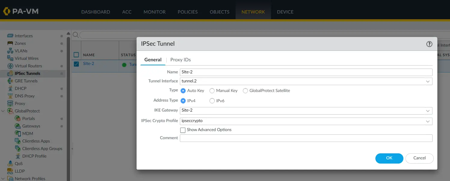
The tunnel interface connects the routing configuration to the IPsec tunnel. The IKE Gateway identifies the remote firewall, while the IPsec Crypto Profile defines how the data is protected.
For additional details on configuring site-to-site IPsec tunnels on PAN-OS, see the official Palo Alto Networks site-to-site IPsec VPN documentation.
What about Proxy IDs?
The Proxy IDs section is empty in this lab.
That is intentional.
This is a route-based VPN between two Palo Alto firewalls. Traffic is routed through the tunnel interface, so we are not configuring Proxy IDs for this lab.
Step 7: Add the Route to the Remote LAN
The VPN can be established successfully and still not carry user traffic if the firewall does not know where the remote network is.
On PA-1, the remote Site-2 network is:
172.20.10.0/24The static route points it to:
Interface: tunnel.2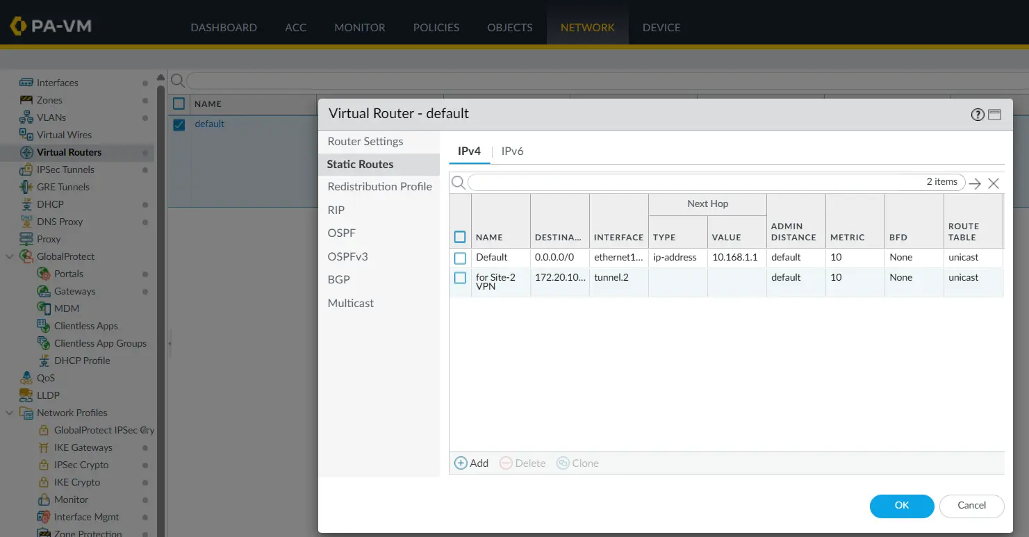
This is what tells PA-1:
Traffic destined for
172.20.10.0/24should use the VPN tunnel.
Without this route, the firewall could have an established VPN but still send the traffic somewhere else.
Step 8: Configure Security Policies
The firewall still needs to permit traffic between the local networks and the VPN zone.
In this lab, we have configured security policies that allow traffic from both the LAN and DMZ zones to the VPN, as well as traffic from the VPN back to the LAN and DMZ zones.
The traffic flow is:
LAN  → VPN
DMZ  → VPN

VPN  → LAN
VPN  → DMZ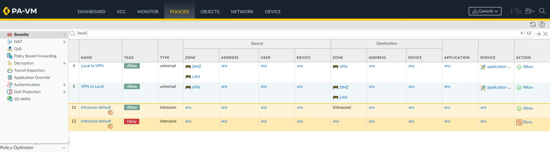
For this lab, the source and destination addresses, applications, and services are configured broadly to simplify testing and verify that the VPN connectivity works correctly.
What should be different in a production environment?
In a production environment, avoid using broad Any-to-Any rules as the final security policy. The policy should follow the least-privilege principle and allow only the communication that is actually required.
For example, if only a specific server in the Site-1 DMZ needs to communicate with a specific server at Site-2, the policy can be restricted to:
Source Zone:          DMZ
Source Address:       172.20.1.10
Destination Zone:     VPN
Destination Address:  172.20.10.20
Application:           Required application
Service:              Required port(s)
Action:               Allow
Similarly, traffic from the VPN back to the local network should be restricted to the required source and destination addresses and services.
Depending on the application requirement, you may also need separate policies for the LAN-to-VPN, DMZ-to-VPN, VPN-to-LAN, and VPN-to-DMZ flows.
The exact policy design depends on which systems need to communicate across the VPN. The important point is that the VPN tunnel provides the encrypted path, while the security policy determines which traffic is actually allowed to use that path.
A tunnel being UP does not automatically mean the security policy will allow traffic through it.
Step 9: Configure NAT
The firewall also has an Internet NAT rule for normal Internet-bound traffic.
For example, the Site-2 NAT configuration shown in the lab is:
Source Zone:      LAN
Destination Zone: WAN
Source Translation: Dynamic IP and Port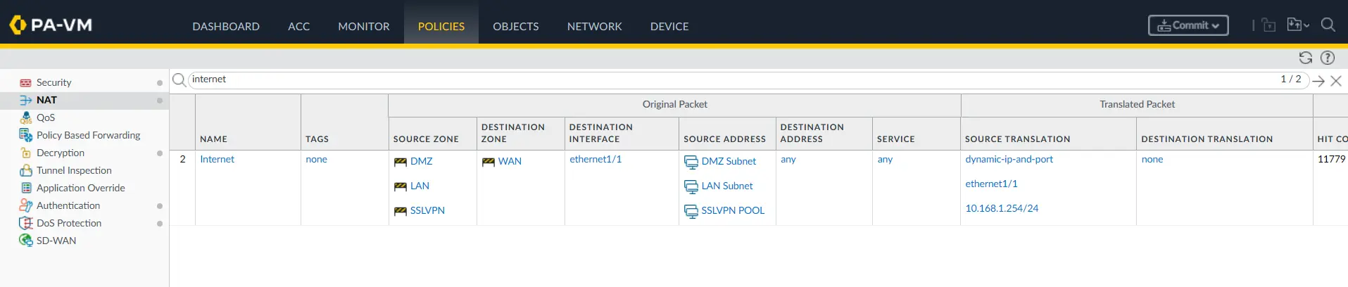
Notice that the Internet NAT rule is associated with the WAN destination zone.
VPN traffic destined for the remote LAN is going toward the VPN zone, not the WAN zone. Therefore, this Internet NAT rule does not match that VPN traffic.
This is an important point in this lab: we don’t need to create a separate NAT rule for VPN traffic simply to prevent the Internet NAT rule from matching it, because the destination zone is different.
Palo Alto Site-2 Configuration
The second firewall uses the same overall design, but the IP addresses and remote network are reversed.
Step 10: Configure Site-2 Interfaces
On PA-2:
ethernet1/1
IP: 10.168.1.250/24
Zone: WAN

ethernet1/2
IP: 172.20.10.254/24
Zone: LAN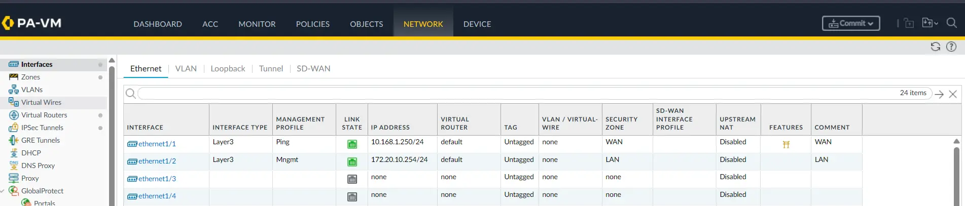
PC-2 uses 172.20.10.254 as its default gateway.
Step 11: Configure Site-2 Tunnel Interface
PA-2 also uses:
Tunnel Interface: tunnel.2
Virtual Router: default
Security Zone: VPN
Both firewalls therefore use tunnel.2 as the logical interface for the route-based VPN.
Step 12: Configure IKE and IPsec
The IKE and IPsec parameters on PA-2 match the configuration on PA-1.
IKE Crypto
DH Group:       group14
Encryption:     aes-256-cbc
Authentication: sha256
Lifetime:       8 hours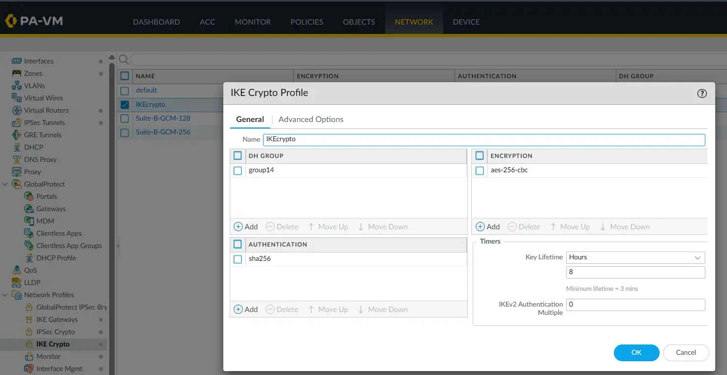
IKE Gateway
PA-2 uses:
Local IP:  10.168.1.250
Peer IP:   10.168.1.254
IKE:       IKEv2 only
Authentication uses the same pre-shared key configured on PA-1.
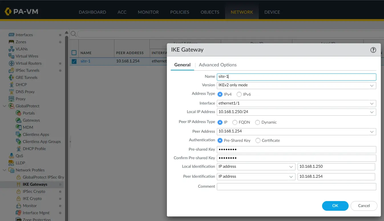
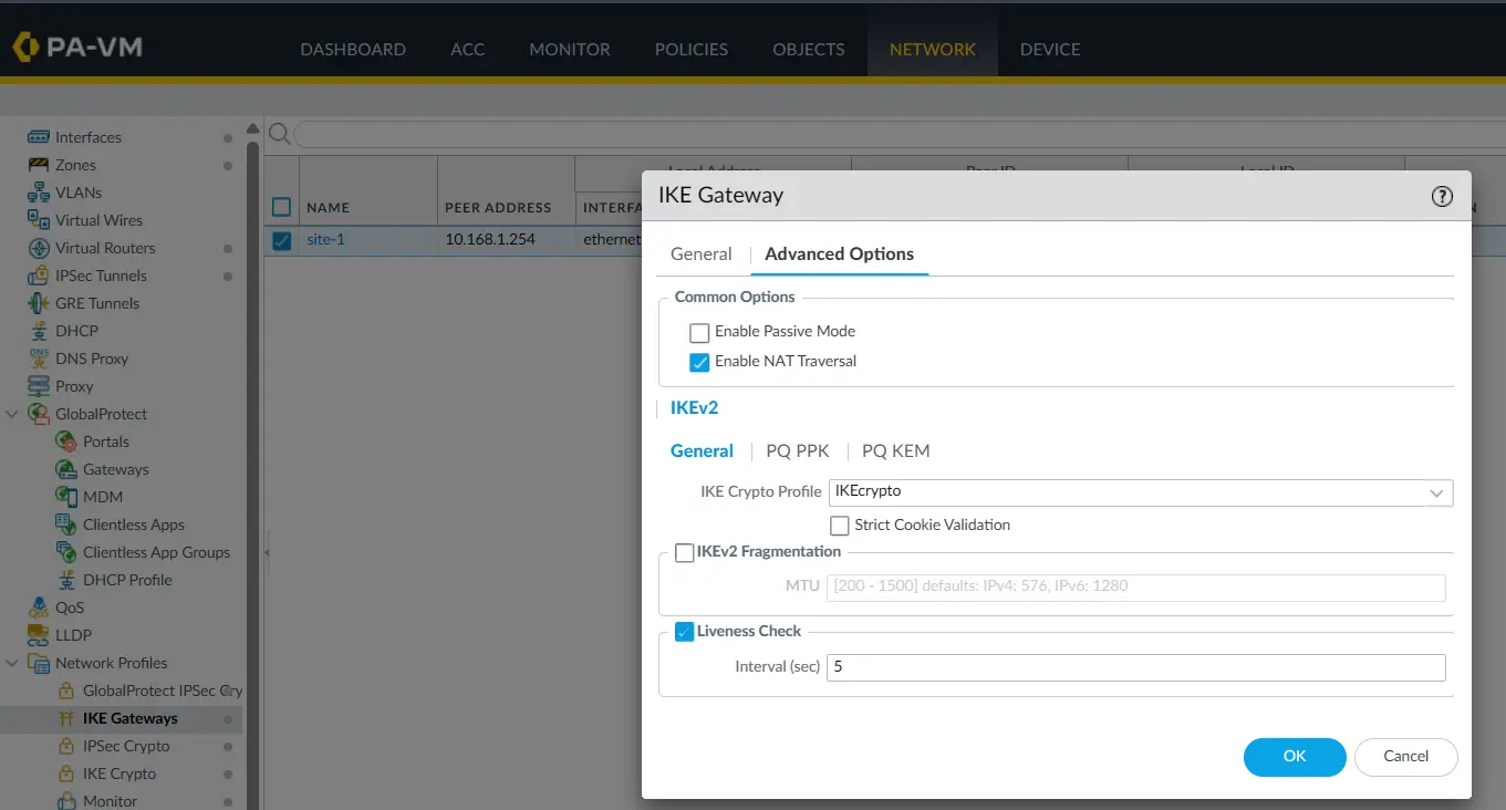
The advanced configuration also has NAT Traversal enabled and IKEv2 liveness checking configured.
IPsec Crypto
PA-2 uses the same IPsec parameters:
Protocol:       ESP
Encryption:     aes-256-cbc
Authentication: sha256
DH Group:       group14
Lifetime:       8 hours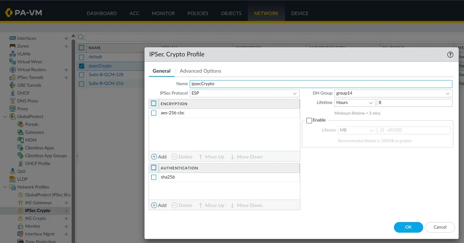
Step 13: Configure the Site-2 IPsec Tunnel
The Site-2 firewall has an IPsec tunnel named Site-1.
It uses:
Tunnel Interface:   tunnel.2
Type:               Auto Key
IKE Gateway:        site-1
IPsec Crypto:       ipsecCrypto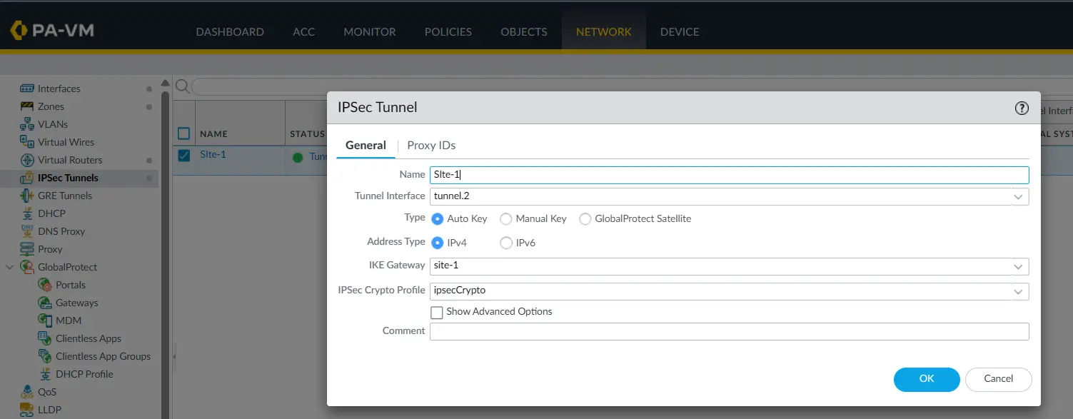
Again, the Proxy IDs section is empty because this is a route-based Palo Alto-to-Palo Alto VPN.
Step 14: Add the Site-1 Route on PA-2
PA-2 needs a route back to the Site-1 DMZ:
Destination: 172.20.1.0/24
Interface:   tunnel.2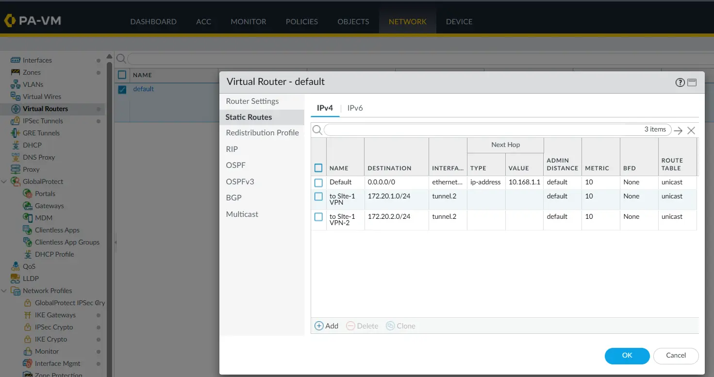
Now both firewalls know where the remote network is:
PA-1:
172.20.10.0/24 → tunnel.2

PA-2:
172.20.1.0/24 → tunnel.2
This gives us the routing path required for bidirectional communication.
Step 15: Configure Site-2 Security Policies
PA-2 has policies allowing traffic between the LAN and VPN zones.
The relevant rules shown in the lab are:
LAN → VPN
VPN → LAN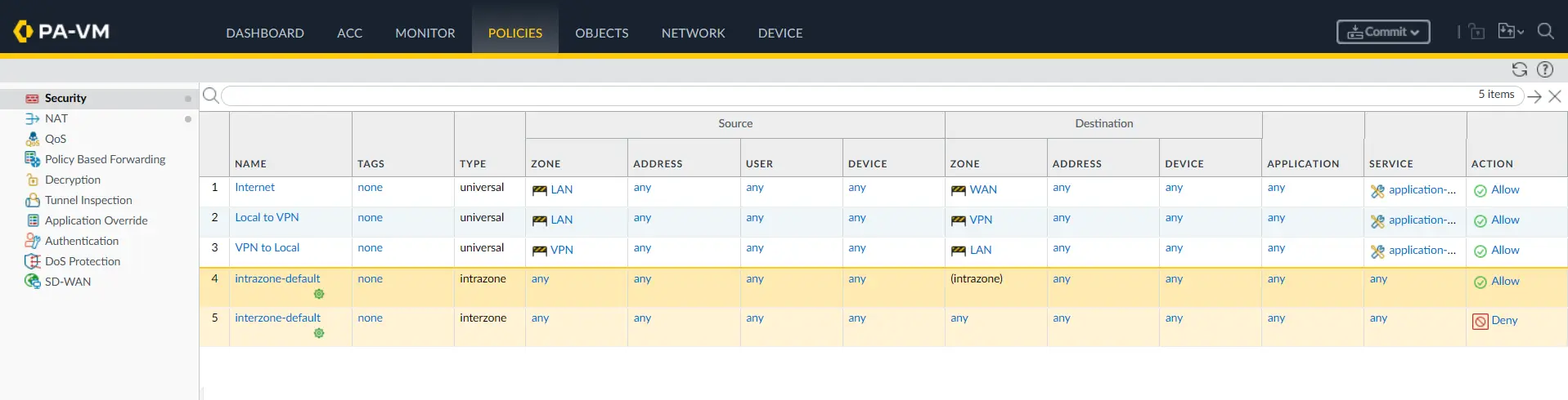
The policy configuration is required even though the IPsec tunnel itself is already established.
Step 16: Verify the IPsec Tunnel
At this point, we can check the IPsec tunnel status.
On PA-2, the IPsec Tunnels page shows the Site-1 tunnel with a green status indicator.
It also shows:
Tunnel Interface: tunnel.2
IKE Gateway:      site-1
Security Zone:    VPN
We can also open the IKE information and confirm that an IKEv2 security association has been established.
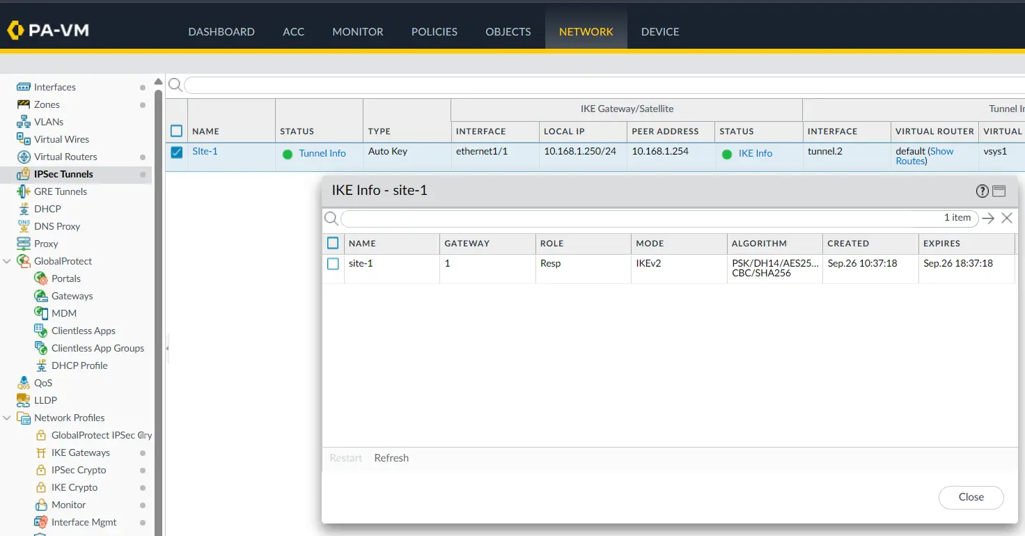
The screenshot shows:
Mode:       IKEv2
Role:       Init
along with the negotiated cryptographic parameters.
Step 17: Check Tunnel Traffic
The tunnel information also shows packet and byte counters.
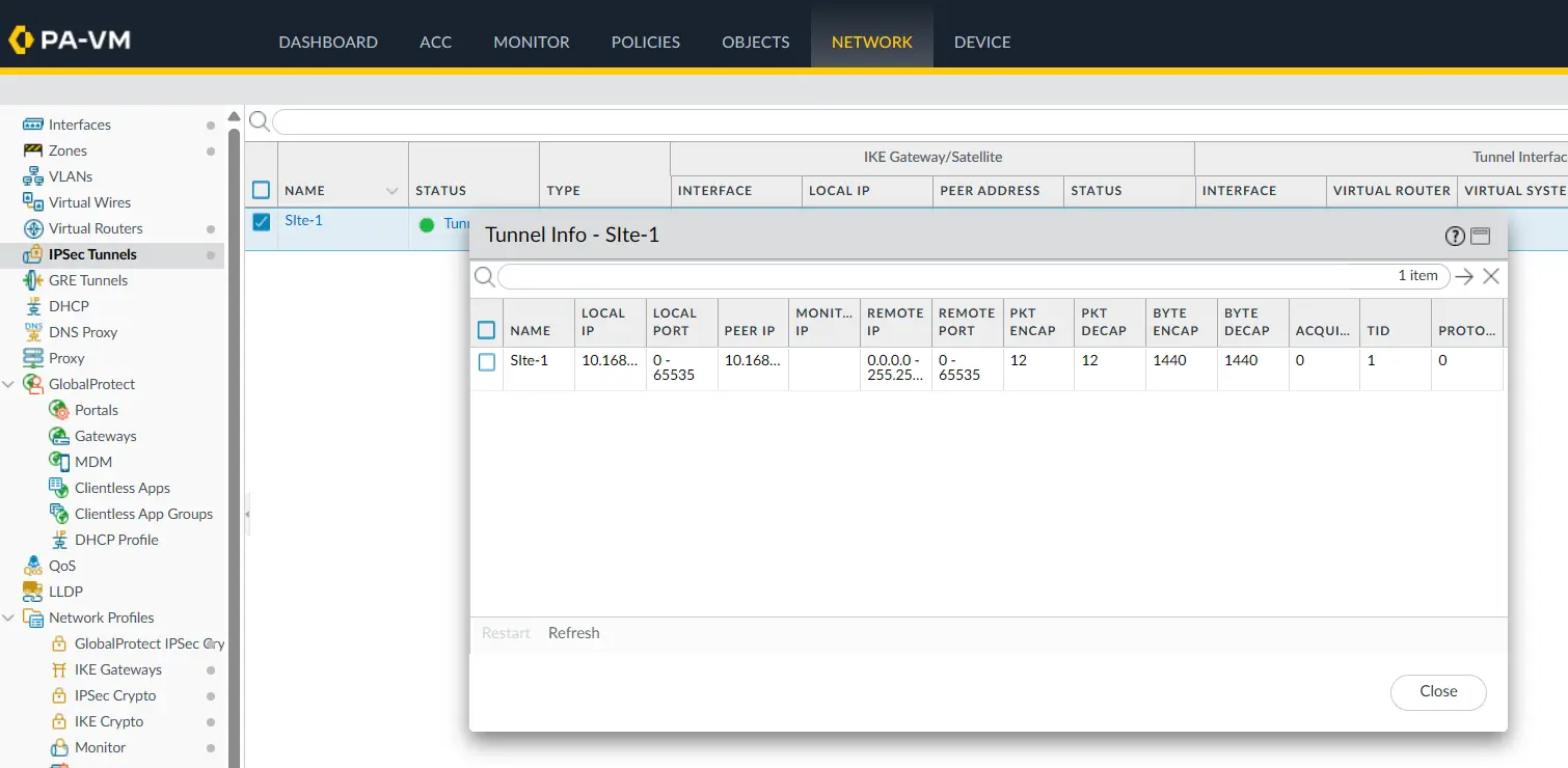
This is useful because a green tunnel status only tells us that the VPN is established.
When traffic actually crosses the tunnel, the encryption and decryption counters should increase.
In this lab, the counters show both encrypted and decrypted traffic, confirming that packets are passing through the IPsec tunnel.
Step 18: Test Connectivity from PC-1
PC-1 is an EVE-NG VPCS node in the Site-1 DMZ with:
IP:      172.20.1.5/24
Gateway: 172.20.1.254
From PC-1, we ping the PC-2 address:
VPCS> ping 172.20.10.5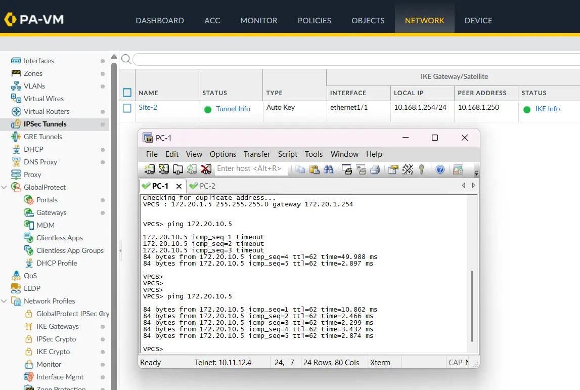
The replies confirm that traffic is successfully travelling from:
172.20.1.5
      ↓
Site-1 DMZ
      ↓
PA-1
      ↓
IPsec VPN
      ↓
PA-2
      ↓
172.20.10.5
Step 19: Test the Return Direction
We can also test the VPN from the Site-2 side.
PC-2 has:
IP:      172.20.10.5/24
Gateway: 172.20.10.254
From PC-2:
VPCS> ping 172.20.1.5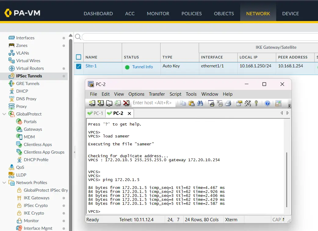
The successful replies confirm that the VPN is working in both directions.
Troubleshooting the Lab
If the tunnel is UP but the ping fails, don’t immediately change the IPsec configuration.
Check the traffic path one piece at a time.
1. Check the route
On PA-1:
172.20.10.0/24 → tunnel.2On PA-2:
172.20.1.0/24 → tunnel.2If the route is missing, the firewall doesn’t know that the remote network should use the VPN.
2. Check the security policy
Make sure the traffic is allowed between:
DMZ → VPN
VPN → DMZ
Also check whether the correct rule is actually being matched.
3. Check NAT
Make sure the Internet NAT rule is not being applied to VPN traffic.
In this lab, the Internet NAT rule uses the WAN destination zone, while VPN traffic is going toward the VPN zone.
4. Check the tunnel status
Verify that:
- IKE SA is established.
- IPsec tunnel is UP.
- Encryption counters increase.
- Decryption counters increase.
5. Check both endpoints
If PC-1 can ping PC-2 but PC-2 cannot ping PC-1, check the return route and reverse security policy on the opposite firewall.
Final Verification Checklist
Before considering the VPN configuration complete, verify these items:
- PA-1 WAN interface is
10.168.1.254/24 - PA-1 DMZ interface is
172.20.1.254/24 - PA-1 LAN network is
172.20.2.0/24 - PA-2 WAN interface is
10.168.1.250/24 - PA-2 LAN interface is
172.20.10.254/24 tunnel.2is assigned to the VPN zone- IKEv2 is configured on both peers
- IKE Crypto parameters match
- IPsec Crypto parameters match
- IKE Gateway points to the correct peer
- IPsec tunnel uses the correct tunnel interface
- Remote LAN/DMZ routes point to
tunnel.2 - DMZ-to-VPN traffic is allowed on Site-1
- VPN-to-DMZ traffic is allowed on Site-1
- LAN-to-VPN traffic is allowed on Site-2
- VPN-to-LAN traffic is allowed on Site-2
- Internet NAT is not matching VPN traffic
- IKE SA is established
- IPsec tunnel is UP
- Encryption/decryption counters show traffic
- PC-1 can ping PC-2
- PC-2 can ping PC-1
Conclusion
There isn’t much mystery once the configuration is separated into the right pieces.
The IKE configuration establishes the relationship between the two Palo Alto firewalls. The IPsec configuration protects the traffic. The tunnel interface gives the firewall a logical path for routing, while the static routes and security policies determine whether the actual DMZ traffic can use that path.
In this lab, the final test is simple: 172.20.1.5 can reach 172.20.10.5, and 172.20.10.5 can reach 172.20.1.5.
That confirms that the VPN is not only UP, but is actually carrying traffic successfully.
Frequently Asked Questions
Do I need Proxy IDs for this Palo Alto VPN?
Not in this lab. Both firewalls are using a route-based IPsec VPN, so the Proxy ID section is left empty and traffic is routed through tunnel.2.
Does an UP IPsec tunnel mean traffic will automatically work?
No. Routing, security policies, NAT behavior, and the return path still need to be correct.
Why is tunnel.2 important?
It is the logical Layer 3 interface used by the route-based VPN. The static routes point remote networks toward this interface.
Why are both DMZ-to-VPN and VPN-to-DMZ policies required?
The VPN needs to allow traffic in both directions. A working IKE/IPsec tunnel does not bypass the firewall’s security policy.

Cybersecurity blogger with a focus on firewalls, network security, and tech trends making security simple for everyone, from IT pros to curious minds.